Nine routes into carbon fibre. Each one is listed with the situation it solves and the situation it does not — because the second half is what tells you whether we are the right supplier.
A supplier list that claims everything tells you nothing. This is our actual shape: eight lines made on our own floor, six quoted only after a sample is accepted, and the part of the chain we do not own.
Raw fibre and carbonisation. Those are the lines that make the fibre, not the parts.
We buy fibre by grade, verify every incoming lot against its certificate, and keep the lot number on the batch record. We do not pretend to own the line that made it.
The distinction matters when you audit us: a factory that owns eight lines and says so is easier to verify than one that lists thirty.
Made on our own floor, from tooling to first article.
You need a long, light, stiff member that carries load along one axis. Tubes and profiled sections replace aluminium or steel where weight per unit length is the cost driver.
Drone arms and landing gear, tripod and light-stand tubes, fishing rod blanks, robot links, machine guarding rails, marine and automotive spars.
Not for impact-loaded or crush structures. A tube is strong along its axis and weak across it — if your load is transverse, this is the wrong product.
Tube sections cut to length and stacked
TUBE
Round tubes wound on the mandrel, grouped before finishing
TUBE
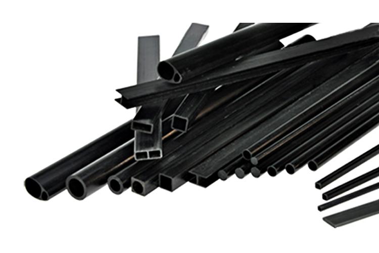
Carbon tube sections in assorted diameters
TUBE
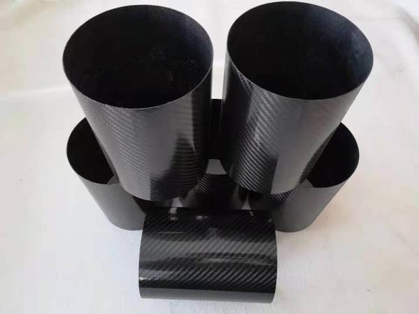
Moulded tube pair
TUBE
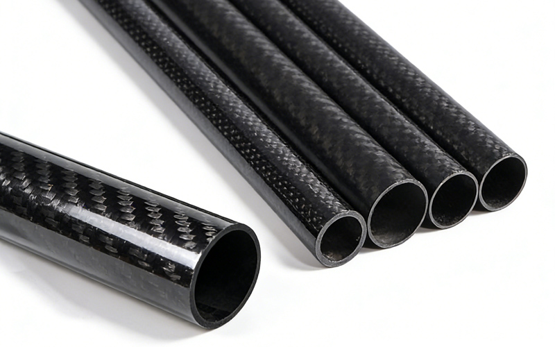
Round tubes grouped before finishing
TUBE
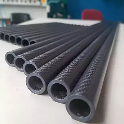
Tube bundle on the shop floor
TUBE
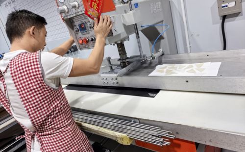
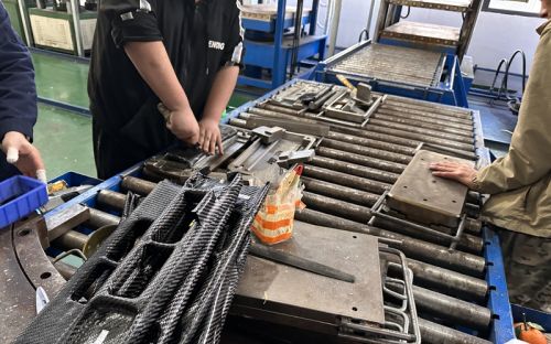
Operator winding fibre onto the mandrel
TUBE| Parameter | Capability |
|---|---|
| Outer diameter | 6 – 400 mm |
| Inner diameter | from 3 mm |
| Length | up to 4 m per piece |
| Sections | round, square, rectangular, tapered, profiled |
| Straightness | ≤0.3 mm/m · ≤0.15 mm/m on request |
| Route | roll-wrap → hot press → cut → end-face grind |
These are the ranges we hold in normal production. Tighter values are quoted per part, and every figure above is measured on the first article report for your batch.
What you get on this line. A written answer to whether it can be made and in what process, a first article report with measured critical dimensions for your first batch, and a video factory walk-through before you commit.
Made on our own floor, from tooling to first article.
You need a flat, stiff panel with holes and cutouts, and the material must not twist or flute when machined. This is the most common industrial request and the one with the widest range of tolerances.
Machine bases, fixtures and jigs, robot end-effectors, inspection equipment, equipment backing plates, drone plates, panels and covers.
Not for large flat panels with hole positions tighter than a laminate can hold — the hole will move. If you need that, we machine a thicker blank or change the design.
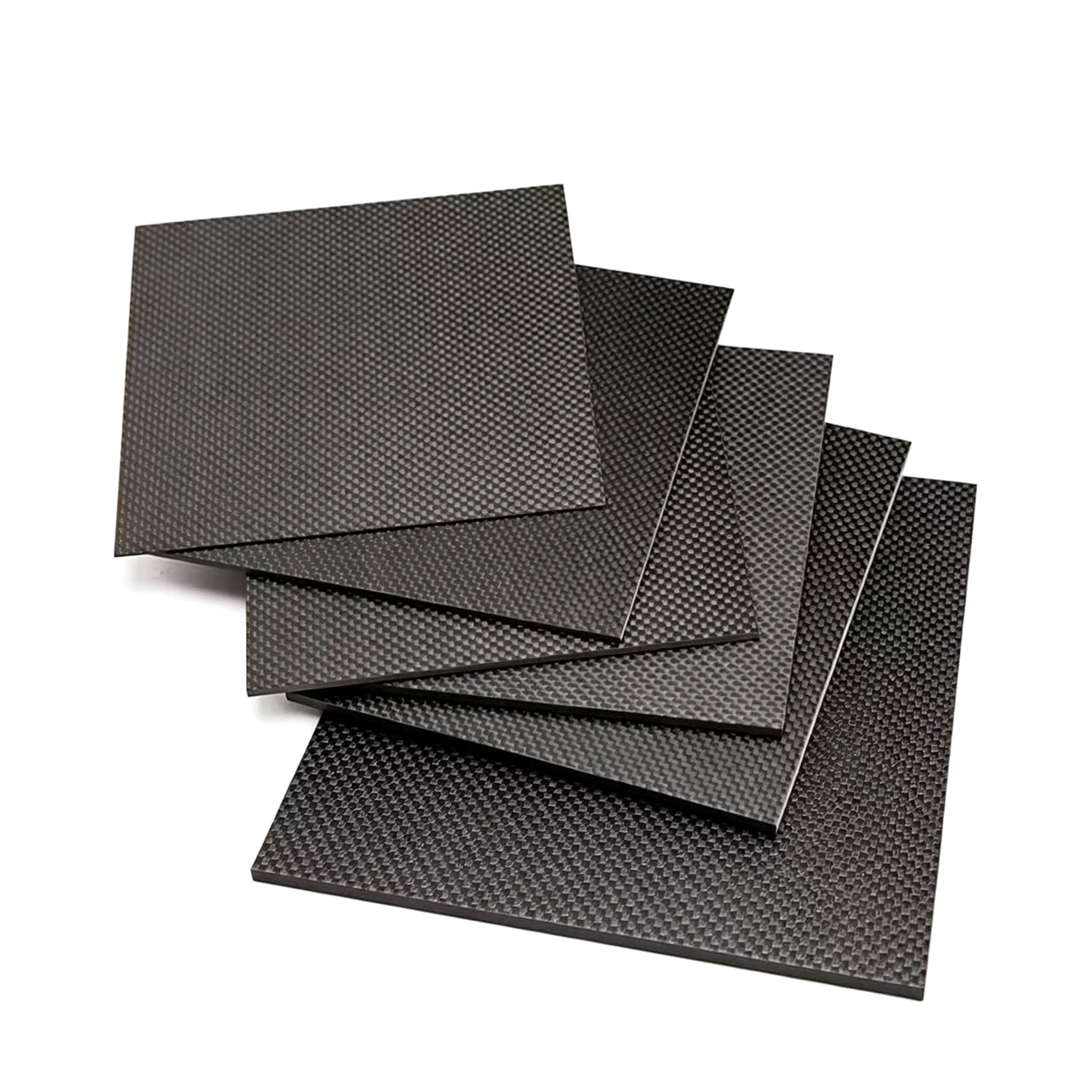
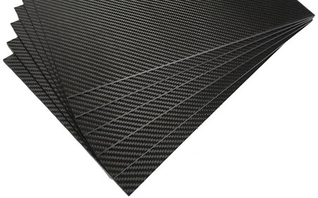
Sheets stacked after the press
SHEET
High-strength carbon sheet
SHEET
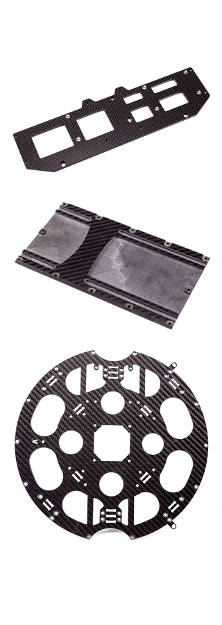
CNC machined carbon parts
SHEET
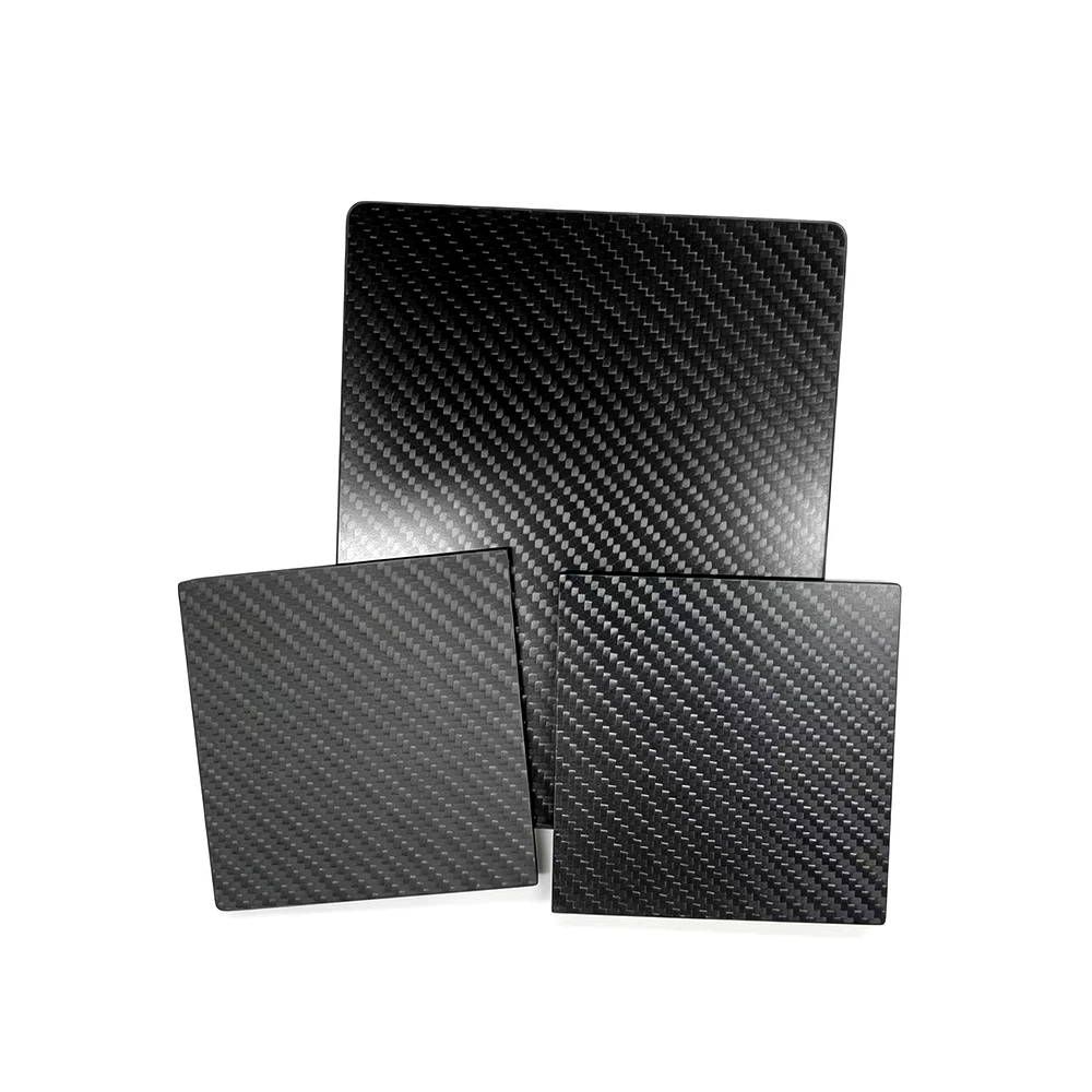
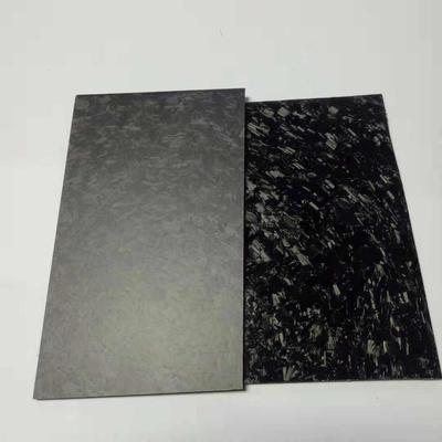
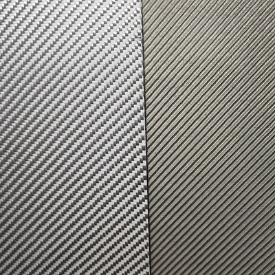
Carbon plate, two layups side by side
SHEET
3K twill weave, close up
SHEET
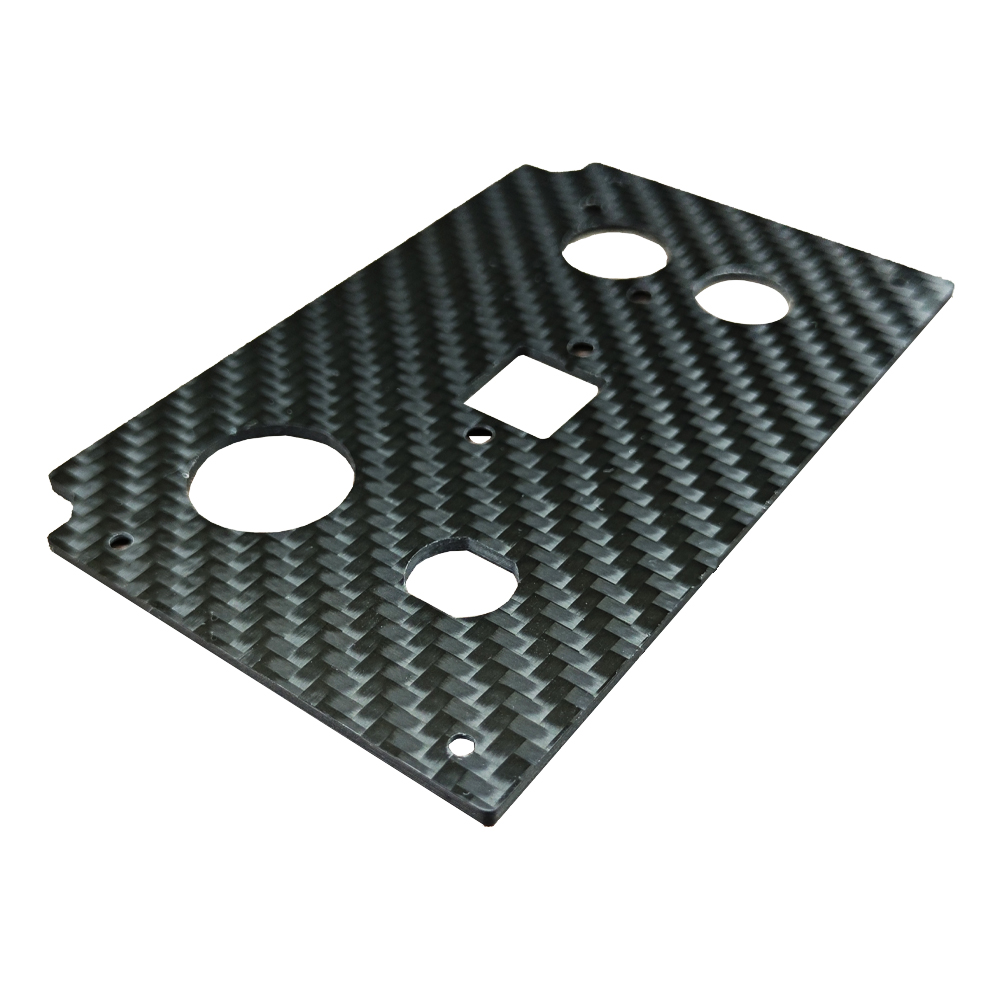
Carbon bracket plate with cut-outs, machined from sheet
SHEET
Plate stock stacked before layup
SHEET| Parameter | Capability |
|---|---|
| Thickness | 0.2 – 50 mm |
| Max sheet size | 3000 × 8000 mm |
| Length / width | ±0.10 mm · ±0.05 tightened |
| Thickness tolerance | ±0.05 mm · ±0.03 tightened |
| Hole position | ±0.10 mm · 0.07 mm measured |
| Flatness | ≤0.20 mm · ≤0.10 tightened |
| Edge squareness | ≤0.5° |
These are the ranges we hold in normal production. Tighter values are quoted per part, and every figure above is measured on the first article report for your batch.
What you get on this line. A written answer to whether it can be made and in what process, a first article report with measured critical dimensions for your first batch, and a video factory walk-through before you commit.
Made on our own floor, from tooling to first article.
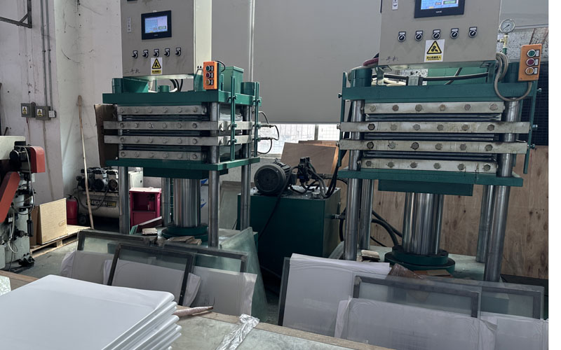
You have a shape that repeats and you need it more than once. Forming moves the cost from per-piece labour into a tool, and that is the only way repeated parts get affordable.
Enclosures and covers, structural modules, industrial housings, drone and robot body parts, fishing reel frames and spools, camera and lighting hardware.
Not for a single part with complex geometry — the tooling cost will exceed the part value. In that case we recommend CNC from plate, or a different material.
Moulded parts stacked after release from the tool
MOLD
Compression press line
MOLD
Part being finished in the tool
MOLD| Parameter | Capability |
|---|---|
| Tooling | matched metal tool, cut in-house |
| First article | 7–15 working days incl. tooling |
| Typical wall | 2.0 ±0.05 mm |
| Flatness | ≤0.20 mm |
| Inserts | hot-pressed, pull-out tested |
| Route | compression mould → CNC trim → balancing |
| Minimum order | 10 pcs |
These are the ranges we hold in normal production. Tighter values are quoted per part, and every figure above is measured on the first article report for your batch.
What you get on this line. A written answer to whether it can be made and in what process, a first article report with measured critical dimensions for your first batch, and a video factory walk-through before you commit.
Made on our own floor, from tooling to first article.
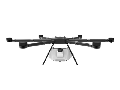
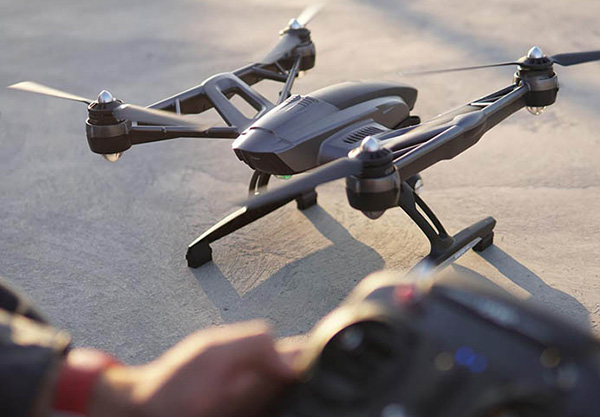
Every gram on an aircraft is paid for twice — once in mass, once in flight time. We build frames and arms around a specified mass target and a specified ply stack.
Multi-rotor frames, arms, landing gear plates, camera and sensor mounts, payload brackets, flight test fixtures.
Not for certified or airworthiness parts. We hold no aviation approval, so we will not take a flight-critical structure and imply the paperwork will follow — we will refer you to a supplier who holds it.
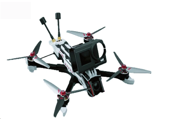
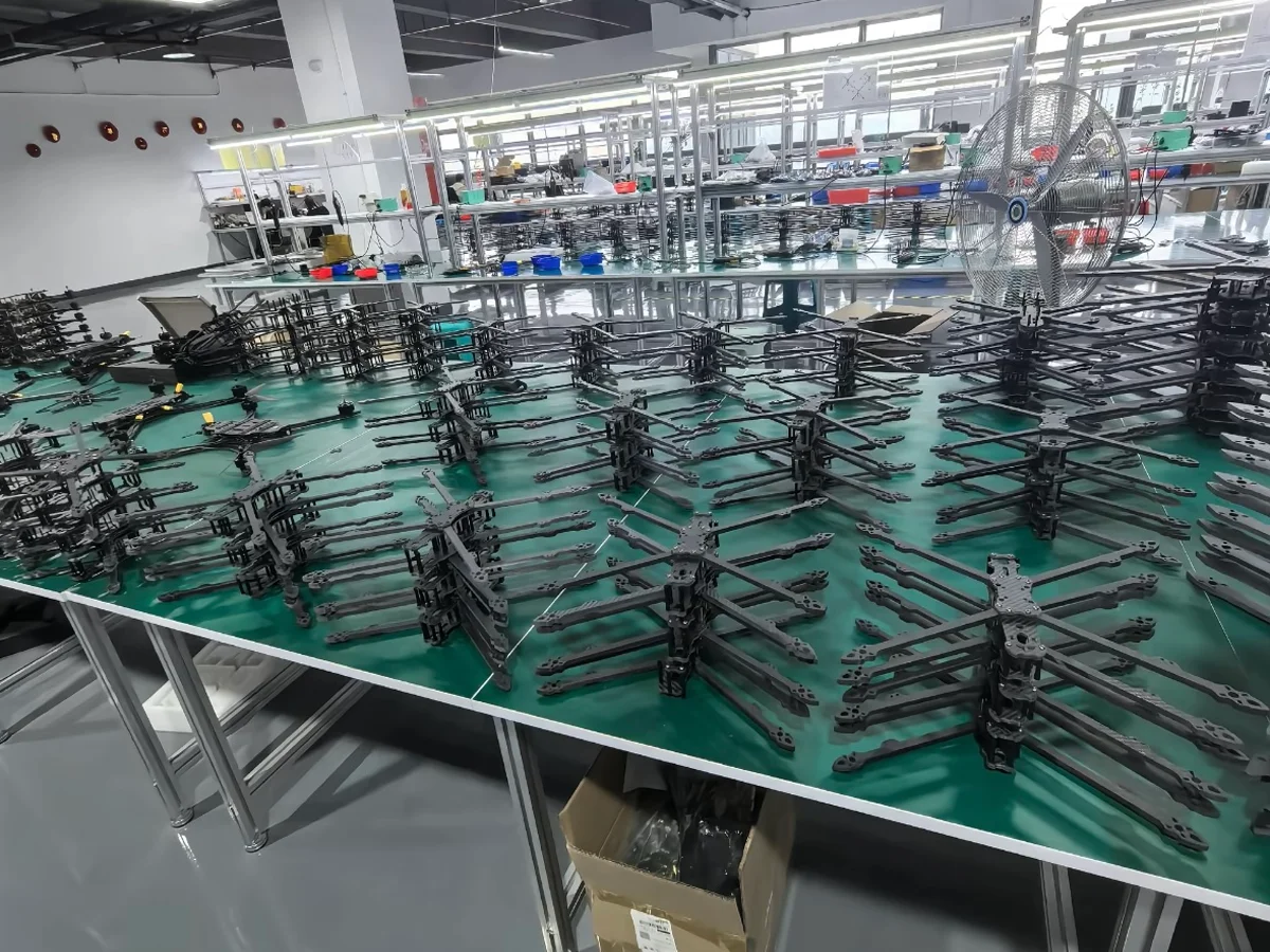
FPV frame in a range of sizes
UAV
Assembled multi-rotor frame
UAV
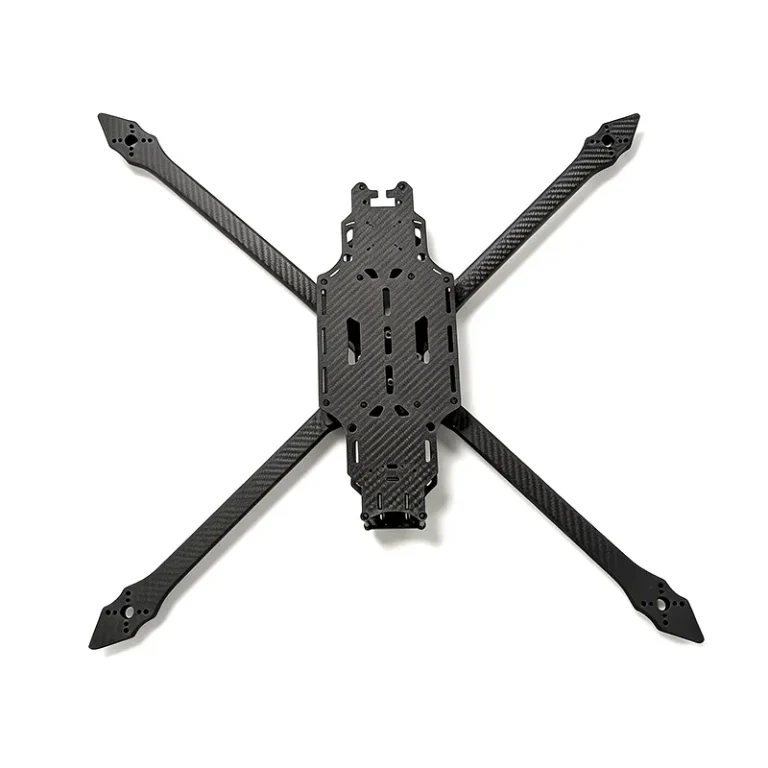
Frame components built to a mass target
UAV
Unmanned aircraft structure
UAV
Assembled UAV
UAV
Drone frame plate, machined
UAV| Parameter | Capability |
|---|---|
| Frame class | 5 – 18 inch |
| Typical plate | 220 × 180 × 3.0 ±0.05 mm |
| Hole position | ±0.10 mm · 0.07 mm measured |
| Ply stack | [0/90/±45]s, T700 3K twill |
| Hardware | embedded inserts, pull-out tested |
| Route | hot press → CNC mill → drill → chamfer |
| Minimum order | 10 pcs |
These are the ranges we hold in normal production. Tighter values are quoted per part, and every figure above is measured on the first article report for your batch.
What you get on this line. A written answer to whether it can be made and in what process, a first article report with measured critical dimensions for your first batch, and a video factory walk-through before you commit.
Made on our own floor, from tooling to first article.
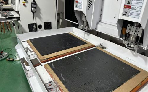
The shape cannot be formed. Undercuts, mixed hole patterns, tight interfaces to another part — these have to come off a machine, and the laminate has to survive the tool.
Complex brackets, housings, adapters, fixtures, robot end-effectors, precision mechanism parts in carbon and epoxy laminate.
Not for deep cavities in thin laminate — the tool has nowhere to bear. We will tell you the minimum wall that holds, and quote the design that works.
Shaped components machined from formed blanks
CNC
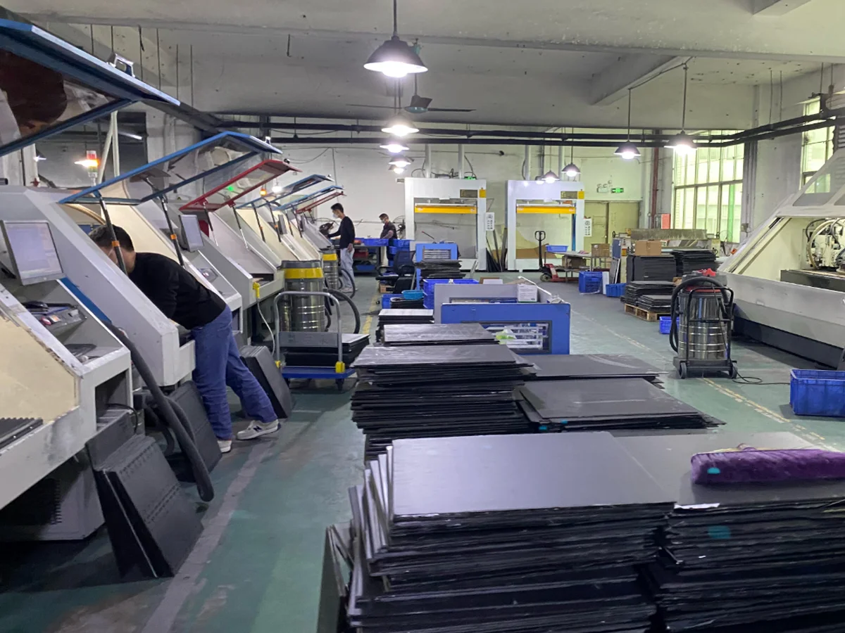
CNC router cutting sheet stock
CNC
Machining cell with sheet stock on the floor
CNC
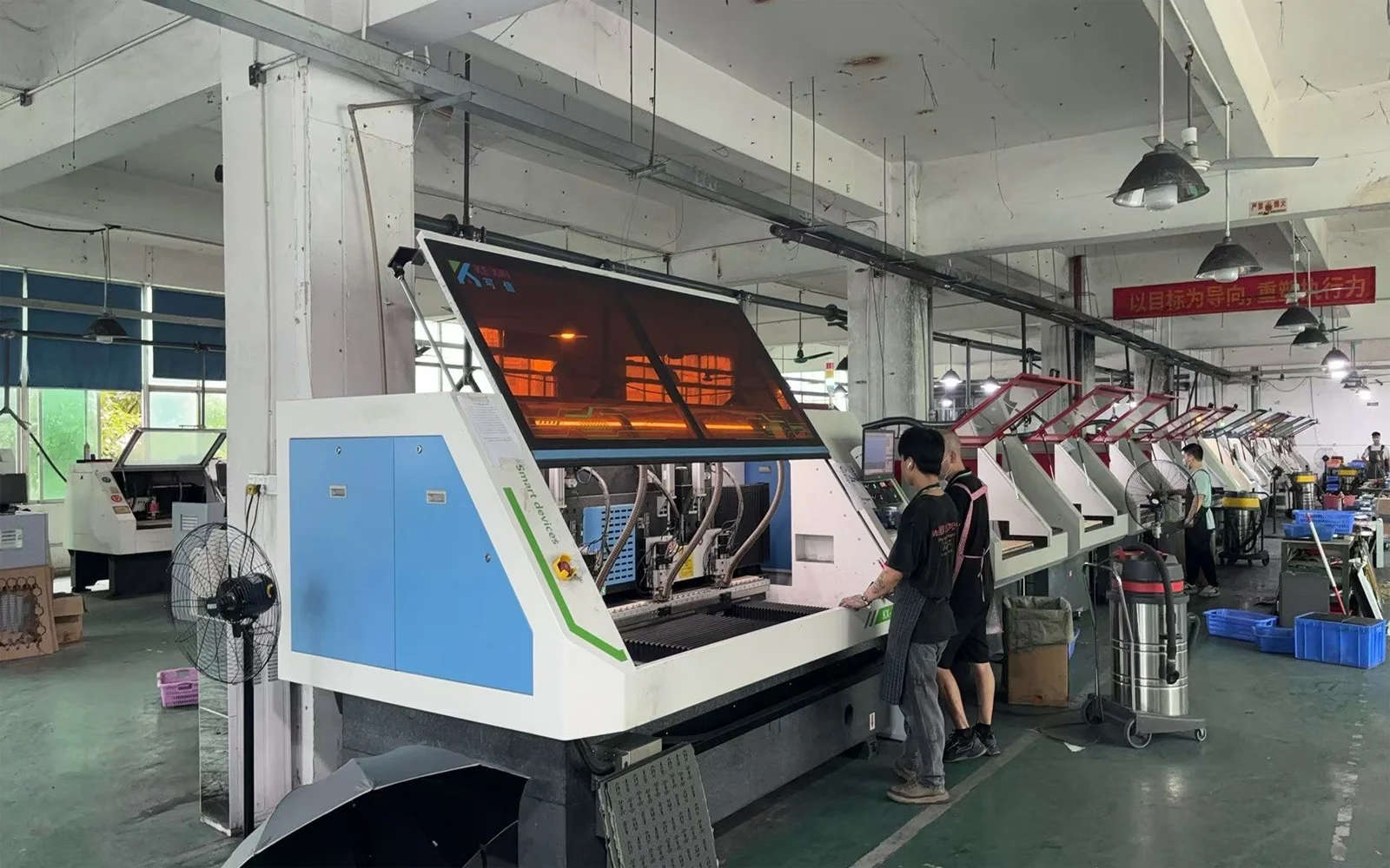
CNC machining centre
CNC
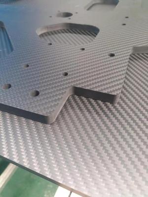
Machined plate with a hole pattern, off the machine
CNC| Parameter | Capability |
|---|---|
| Length / width | ±0.10 mm · ±0.05 tightened |
| Hole position | ±0.10 mm · ±0.05 tightened |
| Smallest feature | per drawing review |
| Bore edge | supported entry, no exit delamination |
| Measured with | CMM and profile projector |
| Dust control | isolated, filtered machining |
These are the ranges we hold in normal production. Tighter values are quoted per part, and every figure above is measured on the first article report for your batch.
What you get on this line. A written answer to whether it can be made and in what process, a first article report with measured critical dimensions for your first batch, and a video factory walk-through before you commit.
We quote this line only after a sample is accepted against your drawing.
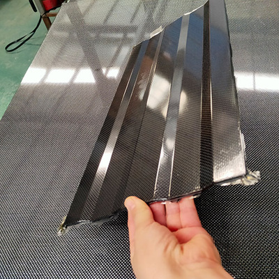
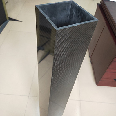
You need the same section over and over, and you need it to be the same every time. Pultrusion holds a constant section continuously — there is no lap, no joint, no variation along the length.
Frames, rails, channels and structural sections for guarding, fixtures, and modular structures.
Not for a section that changes along its length. Pultrusion is a fixed-section process — if your profile varies, that is a formed or machined part.
Profiled sections
SQUARE
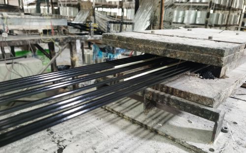
Pultruded profile in production
SQUARE
Pultrusion line pulling continuous profiles
SQUARE
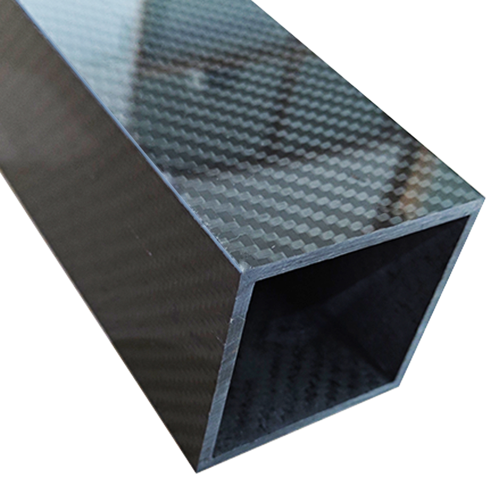
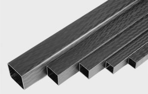
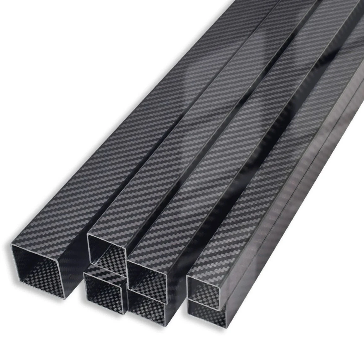
Square section, constant wall, cut to length
SQUARE
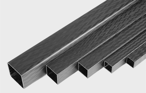
Square sections in a range of wall thicknesses
SQUARE| Parameter | Capability |
|---|---|
| Section | standard or specified |
| Section tolerance | ±0.15 mm on 40 × 40 |
| Wall thickness | per section |
| Length | continuous · cut to 4 m max |
| Straightness | ≤0.3 mm/m |
| Joining | bonded or bolted |
These are the ranges we hold in normal production. Tighter values are quoted per part, and every figure above is measured on the first article report for your batch.
What you get on this line. A written answer to whether it can be made and in what process, a first article report with measured critical dimensions for your first batch, and a video factory walk-through before you commit.
Made on our own floor, from tooling to first article.
A robot part has to do the same thing a thousand times without drifting. That means stiffness that does not change with temperature, and holes that stay where they were put.
Robot arms and links, end-effectors, gripper jaws, axis housings, linear rail covers, automation fixtures and guarding.
Not for very high-cycle production in a fully automated cell — we make the parts, we do not build the cell. For cell integration, use a specialist.
Automation equipment parts
ROBOT
Curved cover panels after forming
ROBOT
Panel section with core
ROBOT
Robot link and arm components
ROBOT
Square section used as a link or housing
ROBOT
Rounded panel, formed
ROBOT| Parameter | Capability |
|---|---|
| Mass | ±2% precision · ±3% structural |
| Hole position | ±0.10 mm |
| Flatness | ≤0.20 mm |
| Interface | to your existing bracket |
| Environment | coolant, dust, washdown — reviewed per part |
| Batch | prototypes to annual volume |
These are the ranges we hold in normal production. Tighter values are quoted per part, and every figure above is measured on the first article report for your batch.
What you get on this line. A written answer to whether it can be made and in what process, a first article report with measured critical dimensions for your first batch, and a video factory walk-through before you commit.

We quote this line only after a sample is accepted against your drawing.
Automotive does not buy a good part, it buys the same part ten thousand times. The question is not whether one piece is right — it is whether piece number nine thousand is the same as piece number one.
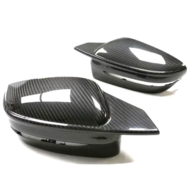
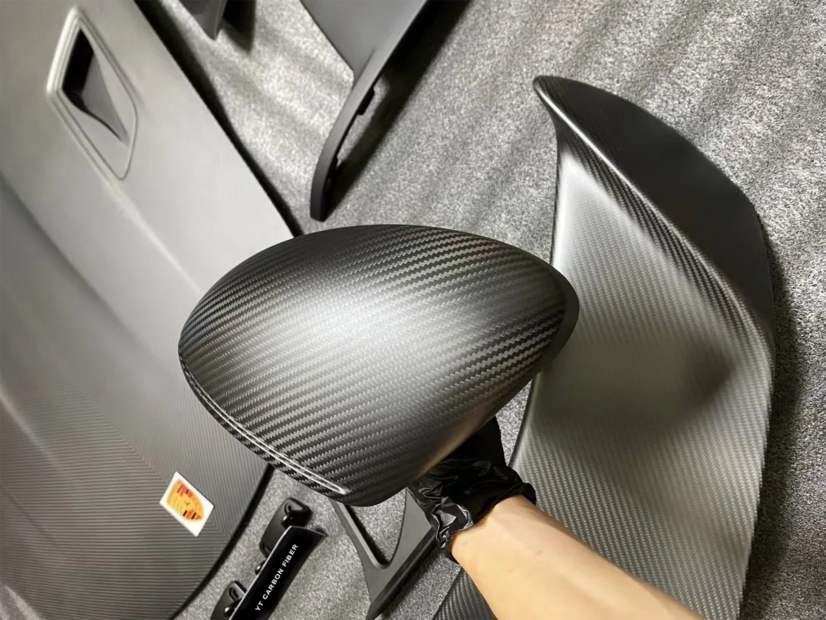
Interior and exterior trim, mirror covers, spoilers, brackets, aftermarket appearance parts.
Not for primary safety structures, and not for anything needing automotive homologation. We make trim and appearance parts, not type-approved components.
Vehicle production line
AUTO
Carbon mirror covers and spoilers
AUTO| Parameter | Capability |
|---|---|
| Appearance class | A to C, against a signed sample |
| Coating | paint, clear or coating — signed sample first |
| Thickness | ±0.05 mm |
| First article | 7–15 working days incl. tooling |
| Documentation | FAI report, material COA, batch record |
| Batch consistency | recorded per batch |
These are the ranges we hold in normal production. Tighter values are quoted per part, and every figure above is measured on the first article report for your batch.
What you get on this line. A written answer to whether it can be made and in what process, a first article report with measured critical dimensions for your first batch, and a video factory walk-through before you commit.
We quote this line only after a sample is accepted against your drawing.
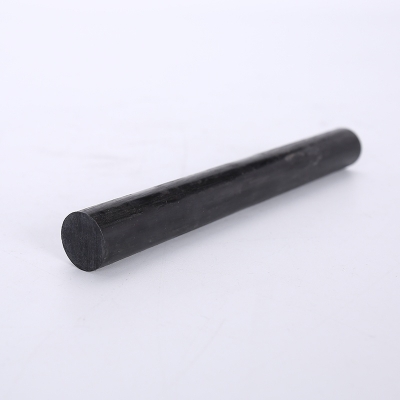
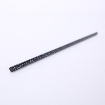
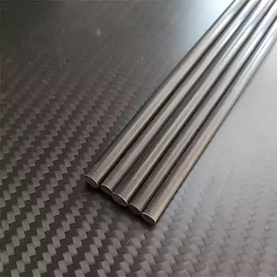
You need stiffness in one direction with almost no weight, and you are not building a hollow structure. Solid rod gives the highest stiffness per gram in a simple round section.
Sensor and probe mounts, small linkages, precision shafts, antenna and equipment mounts, tooling handles.
Not for high-load structural members — a solid bar is heavy for the stiffness it adds. Use a tube and put the material where the load is.
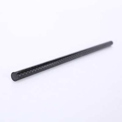
Solid round rod, machined to length
ROD
Thin round rod
ROD
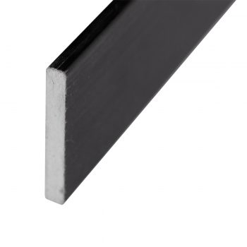
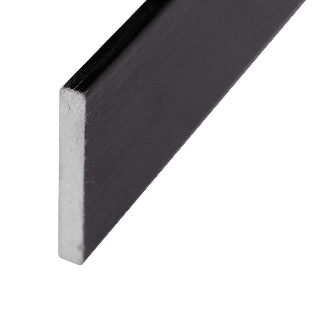
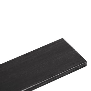
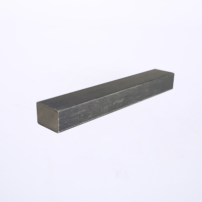
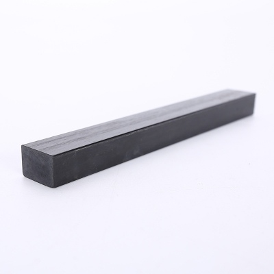
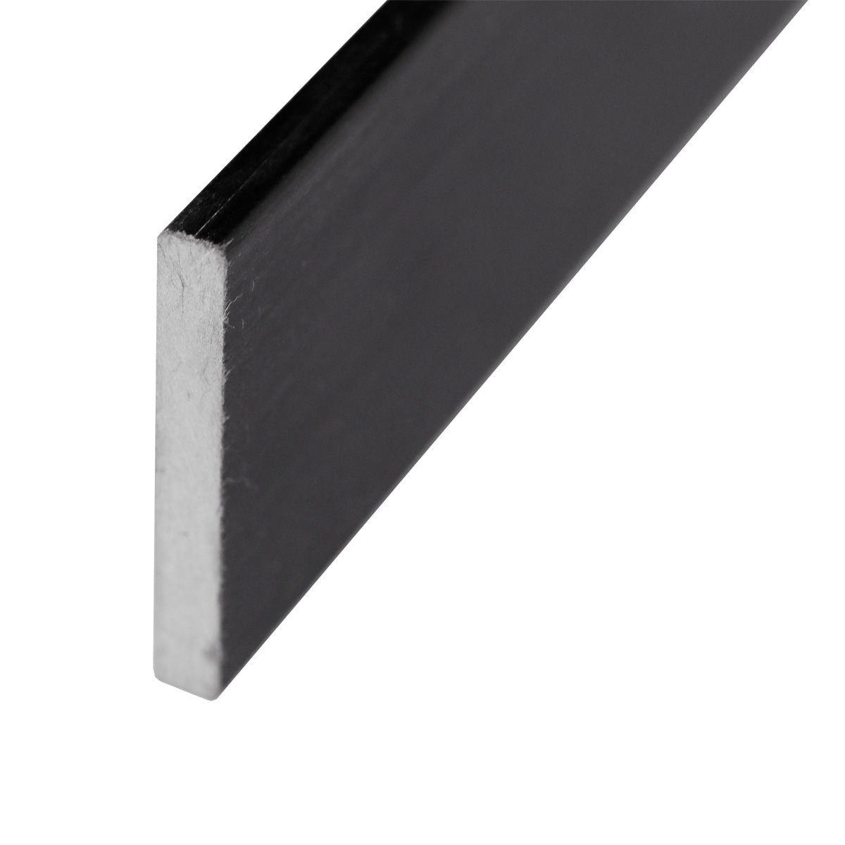
Rectangular bar
ROD
Square bar section
ROD
Faceted bar section
ROD
Rod stock bundled for despatch
ROD| Parameter | Capability |
|---|---|
| Diameter | 0.5 – 50 mm |
| Length | cut to your dimension |
| Straightness | ≤0.3 mm/m |
| Finish | ground or as-produced |
| Density | 1.7 – 1.8 g/cm³ |
| Minimum order | 10 pcs |
These are the ranges we hold in normal production. Tighter values are quoted per part, and every figure above is measured on the first article report for your batch.
What you get on this line. A written answer to whether it can be made and in what process, a first article report with measured critical dimensions for your first batch, and a video factory walk-through before you commit.